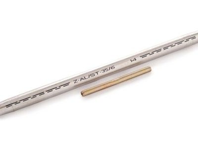
Description
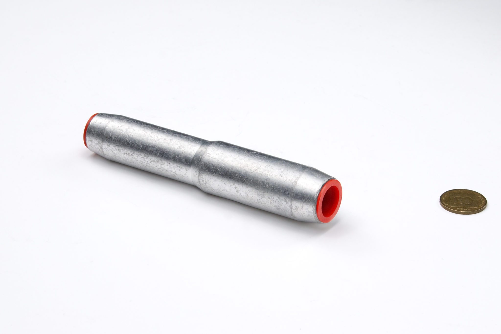
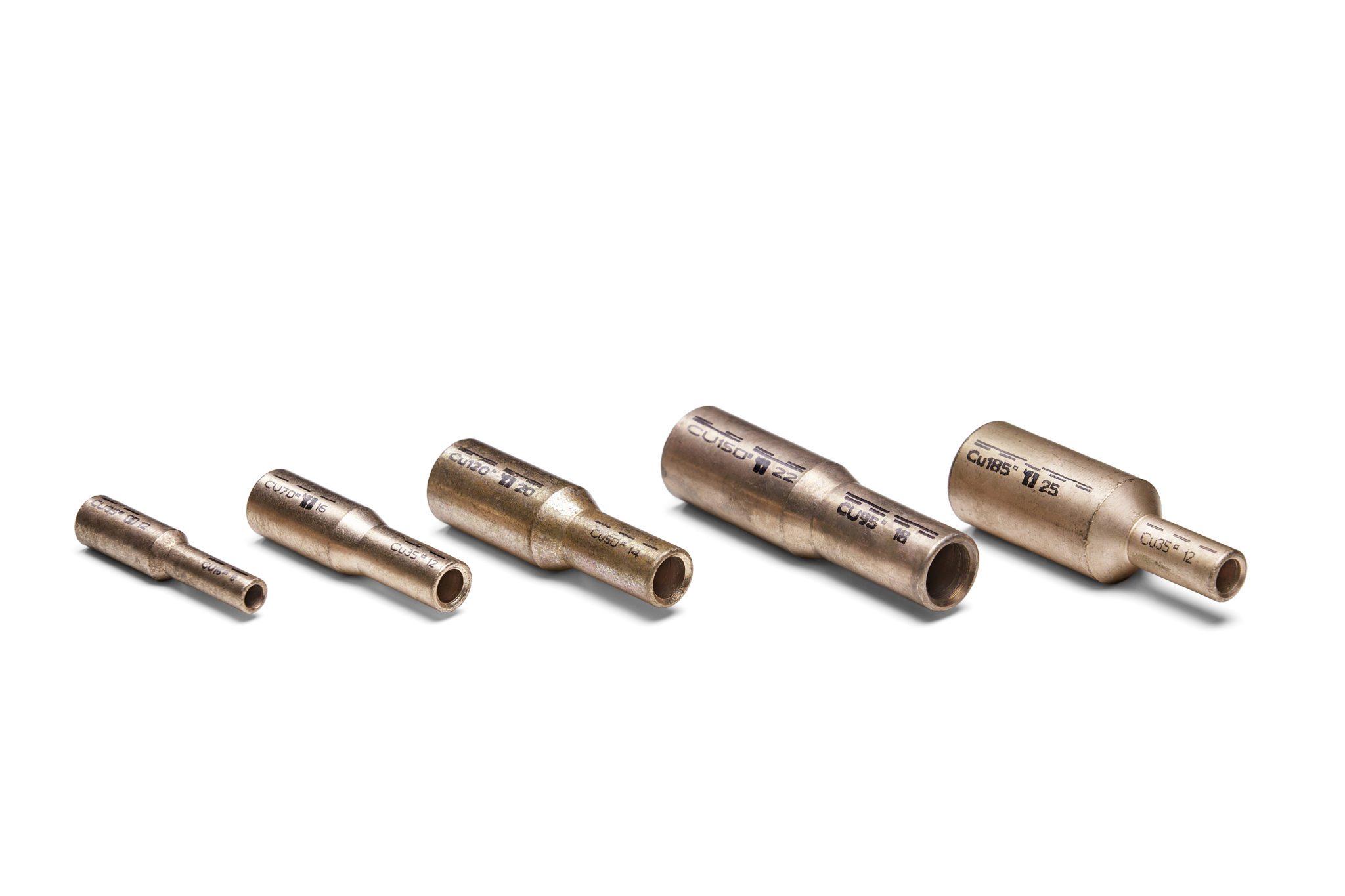
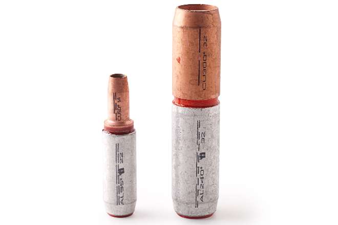
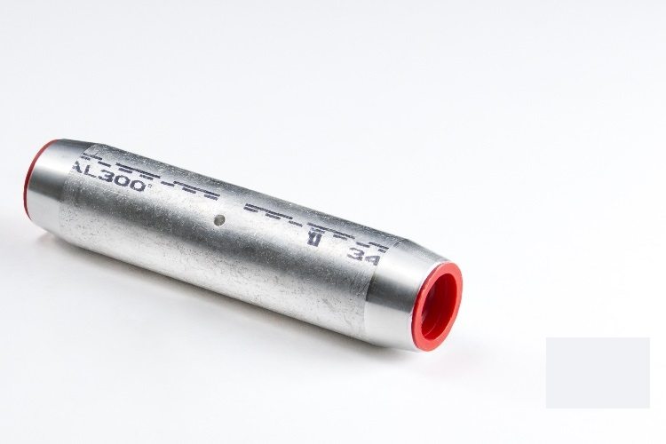
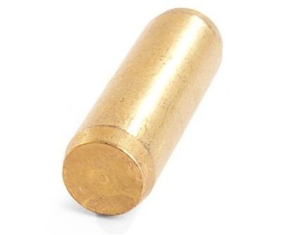
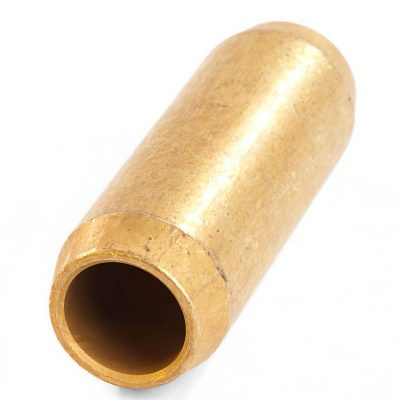
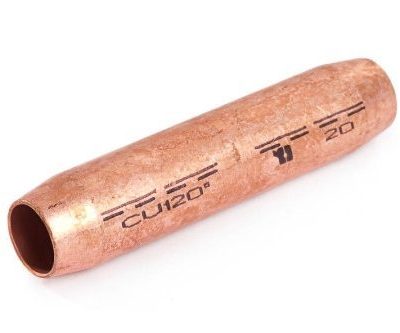
For high voltage cables with blind-hole. For non-tension connections of high-voltage cables. The compression joints are suitable for paper and plastic-insulated cables. They bear double markings and can be either round compressed or hexagonally compressed, depending on cable type and voltage level.Material
AluminiumSurface:
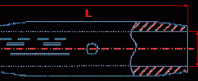
Uncoated| Cat. No. | Conductor Cross-Section sq. mm | Conductor Ø mm | Die Code No. | Dimensions mm. | No of Compressions | Weight 100 Pcs. Kg. |
||||
|---|---|---|---|---|---|---|---|---|---|---|
| d1 | d2 | l | l1 | mech. | hydr. | |||||
| 101305748 | 25 | |||||||||
| 101305749 | 35 | 6.6-7.8 | 14 | 8.0 | 14 | 95 | 43 | 4-4 | 2-2 | 5.1 |
| 101305750 | 50 | 7.7-8.6 | 16 | 9.8 | 16 | 95 | 43 | 4-4 | 2-2 | 3.5 |
| 101305751 | 70 | 9.3-10.2 | 18 | 11.2 | 18.5 | 100 | 45 | 4-4 | 2-2 | 9.3 |
| 101305752 | 95 | 11.0-12.0 | 22 | 13.2 | 22 | 105 | 47 | 4-4 | 2-2 | 8.6 |
| 101305753 | 120 | 12.5-13.5 | 22 | 14.7 | 23 | 110 | 49 | 4-4 | 2-2 | 8.3 |
| 101305754 | 150 | 13.9-15.0 | 25 | 16.3 | 25 | 110 | 49 | 4-4 | 2-2 | 9.9 |
| 101305755 | 185 | 15.5-16.8 | 28 | 18.3 | 28.5 | 130 | 57 | 5-5 | 2-2 | 14.9 |
| 101305756 | 240 | 17.8-19.2 | 32 | 21.0 | 32 | 130 | 57 | 5-5 | 2-2 | 18.3 |
| 101305757 | 300 | 20.0-21.6 | 34 | 23.3 | 34 | 135 | 59 | 5-5 | 2-2 | 19.9 |
User Instructions:
The compression joints are marked with a code number in front of the logo (roughly corresponding to the outer diameter of the compression sleeve). The required compression die is selected in accordance with this code number. For hexagonal compressions made with hand-operated mechanical compression tools, browned dies (black) are to be used for copper, bronze and steel compression joints, whereas aluminium compression joints require electro-galvanized dies (white). For hydraulic compression tools there is no differentiation of dies for different metals. The compression sleeve non-tension and full-tension of aluminium compression joints and of full-tension copper compression joints are prefilled with compression compound which must not be removed before the compression, neither completely nor in part. Any compression compound escaping during the compression should be wiped off.Assembly Instructions:
- Clean the conductor or cable ends with a wire brush to remove dirt and oxidation.
- Insert conductor or cable ends into the compression sleeve up to the centre.
- Before proceeding, make sure that the code number on the compression joint is matched to that on the compression die.
- Compression joints are compressed by making the first compression at the centre and working out toward the ends. The number of compressions is marked on the sleeve. It is important to make the specified number of compressions.

